Previous section

️ ← HDX placement

HDX installation BETA

Nureva HDX audio bars and microphone pod from the back to show easy installation options for vertical, horizontal and VESA mounting.

The HDX user guide is in three parts. This third section covers the steps for physically installing and setting up your Nureva® HDX system, including mounting the components, connecting the cables and running an update.

Audio bar installation

The audio bar can be installed vertically or horizontally on the wall with the mounting bracket provided. A portable stand with VESA® standard mounting may also be used.

✍️ Note Ensure you review Audio bar placement requirements before installation.
Rear view of the Nureva HDX audio bar in vertical orientation showing the mounting bracket placement.

Vertical

Rear view of the Nureva HDX audio bar in horizontal orientation showing the mounting bracket placement.

Horizontal

Rear view of the Nureva HDX audio bar with a close-up callout of the VESA mounting pattern.

VESA

The installation steps for both vertical and horizontal orientations on the wall are provided below.

What’s in the box

Nureva HDX audio bar shown at an angle as an in-box component.

Audio bar

Nureva HDX audio bar wall mount bracket included in the box.

Mounting bracket

Nureva HDX audio bar mounting template used to mark drill holes.

Mounting template

What you’ll need

  • CAT5e or higher Ethernet cable: See Ethernet cable requirements.
  • Screwdriver
  • Drill
  • Anchors: #10 panhead or M5 panhead minimum (x2)
  • Screws: #10 panhead or M5 panhead minimum (x2)
  • Pencil or pen for marking
  • Ladder, level and tape measure

Wall mount — vertical and horizontal

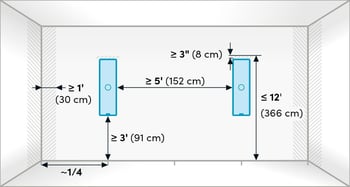
1. Plan the mounting location

Select an appropriate location on the wall for installation.

See HDX placement for guidance on locations.

Diagram of recommended wall placement dimensions and clearances for the Nureva HDX audio bar within a room.

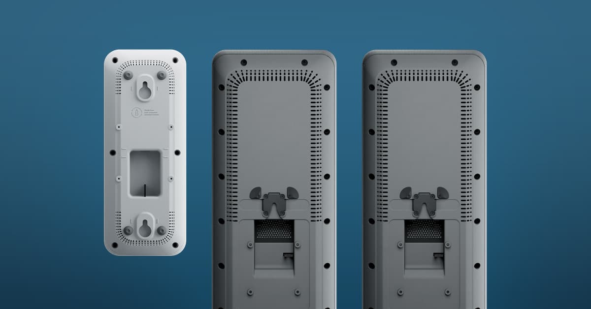
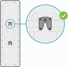
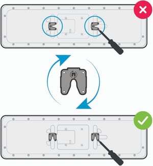
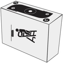
2. Choose orientation

Vertical orientation:

The mounting squares on the back of the audio bar come pre-attached for vertical mounting, with the notches facing the floor.

Diagram showing the correct mounting clip orientation (check mark) for installing the Nureva HDX audio bar vertically.

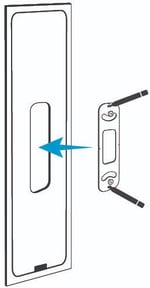
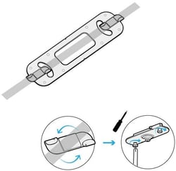
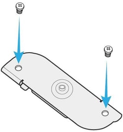
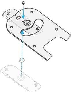
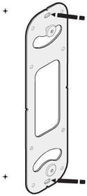
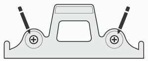
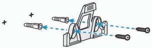
Horizontal orientation:

Hardware adjustment is required to install the audio bar in the horizontal position:

  • Remove the four screws from each mounting square.
  • Rotate each mounting square to position it for horizontal installation, ensuring notches face downward.
  • Reinsert the screws in the new orientation.

Diagram showing how to rotate the Nureva HDX audio bar mounting clips into the correct orientation for horizontal installation, with an incorrect (X) and correct (check) position.

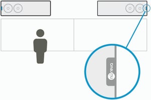
✍️ Note: For horizontal installation, ensure the Nureva logo on each audio bar is positioned at opposite ends, facing away from each other. The speakers are positioned near the Nureva logo, and this arrangement ensures proper speaker dispersion across the room.

Person standing in front of a wall-mounted Nureva HDX audio bar installed in horizontal orientation, with a close-up of the logo placement.

3. Mark for installation

Use the mounting template provided to aid installation.

  • Insert the mounting bracket inside the center cutout of the mounting template.
  • Hold the template and bracket against the wall in the chosen location.
  • Trace the two center oblong holes in the mounting bracket with a pencil or pen to mark drill points.
  • Remove the template.
Diagram showing the mounting template aligned with the wall mount bracket on the Nureva HDX audio bar.

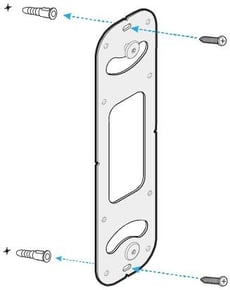
4. Install the mounting bracket

Ensure the drill points are level vertically, drill the holes, insert wall anchors if needed and secure the mounting bracket with screws.

Nureva HDX audio bar wall mount bracket being secured to the wall with screws and wall anchors.

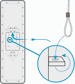
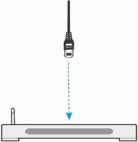
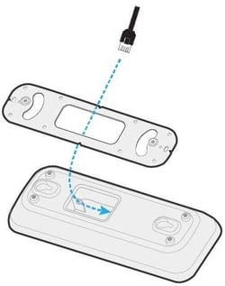
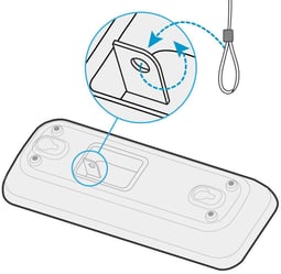
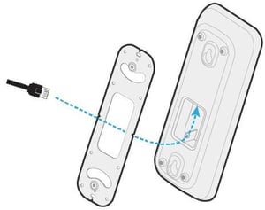
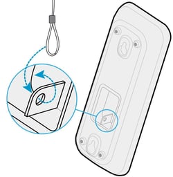
5. Route the Ethernet cable

Run the Ethernet cable to the mounting area and plug it into the back of the audio bar before mounting it on the wall.

💡 Tip: For added security, you can attach a security wire or tether through the small hole in the metal frame on the back of the audio bar.

Rear view of the Nureva HDX audio bar with a close-up showing how to route the Ethernet cable through the mounting channel.

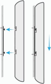
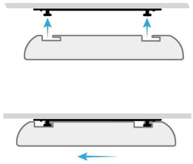
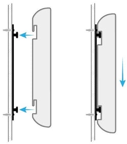
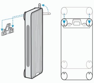
6. Mount the audio bar

Align the audio bar mounting squares above the pegs on the mounting bracket. Slide the audio bar downward until it’s secured in place.

Side-view diagram showing the Nureva HDX audio bar being lowered onto its wall mount bracket.

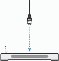
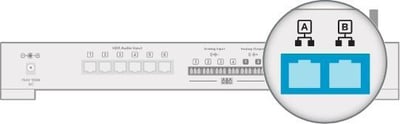
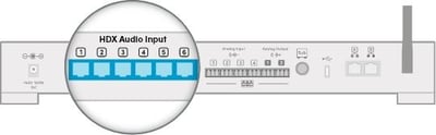
7. Connect to system hub

Connect the other end of the Ethernet cable to one of the HDX audio input ports on the system hub.

See Connecting components.

Ethernet cable connecting the Nureva HDX audio bar down to the HDX system hub.

VESA mount

HDX audio bars may be installed using VESA standard mounts (display mounts, floor stands or mobile carts). Follow the mount manufacturer’s instructions. All the applicable vertical and horizontal installation guidelines above still apply — a VESA standard mount may be used in place of the wall mount bracket but the positioning, clearance and orientation guidelines should still be followed.

Mounting considerations:

  • Verify the mount is rated to support the weight of the HDX audio bar.
  • Ensure stability in both vertical and horizontal orientations.
  • For floor stands, confirm the base is stable and resistant to vibration.
  • Always follow the mount manufacturer’s specifications.

Audio bar FAQs

Can I install the HDX audio bar horizontally?

Yes. The HDX audio bar can be installed vertically or horizontally. Horizontal installation requires rotating the mounting squares on the back of each audio bar so the notches face downward. For each pair of audio bars, ensure the Nureva logos are at opposite ends, facing away from each other, for proper speaker dispersion.

What type of Ethernet cable does the HDX audio bar require?

Each HDX component (audio bar and microphone pod) requires an Ethernet cable that meets the following specifications: CAT5e or higher, unshielded twisted pair (UTP) and 24 AWG (solid copper). Nureva recommends using cabling and wiring that is in accordance with the applicable national, regional and local electrical codes or ordinances.

Microphone pod installation

The microphone pod can be installed on the ceiling or on the wall with the mounting bracket provided. A portable stand with VESA standard mounting may also be used.

✍️ Note Ensure you review Microphone pod placement requirements before installation.
Ceiling mount placement guide template for the Nureva HDX microphone pod.

Ceiling mounted

Wall mount placement guide template for the Nureva HDX microphone pod.

Wall mounted

Nureva HDX microphone pod VESA mount compatibility diagram with a close-up of the VESA pattern.

VESA

What’s in the box

Nureva HDX microphone pod shown at an angle as an in-box component.

Microphone pod

Nureva HDX microphone pod mounting bracket included in the box.

Mounting bracket

Two T-bar clips included with the Nureva HDX microphone pod.

T-bar clips x2

Set of six screws included with the Nureva HDX microphone pod.

M3 panhead screws x6

Adhesive washer included with the Nureva HDX microphone pod.

Wave washers x2

What you’ll need

Additional items when mounting to wall or directly to ceiling:

  • Drill
  • Anchors: #10 panhead or M5 panhead minimum (x2)
  • Screws: #10 panhead or M5 panhead minimum (x2)
  • Pencil or pen for marking

Ceiling mount

✍️ Note T‑bar clips are used to attach the mounting bracket to the main tees or cross tees of a suspended (T‑bar) ceiling grid.

1. Plan the mounting location

Choose a suitable location on the ceiling for optimal audio pickup.

Refer to HDX placement for guidance on locations.

Ceiling mount placement guide template for the Nureva HDX microphone pod.

2. Attach T-bar clips to the mounting bracket

  • Retrieve the T-bar clips from the packaging.

Step 2 of ceiling installation: Attach T-bar clips to the mounting bracket.

  • Insert two screws into the side holes of each T-bar clip.

✍️ Note: Do not fully tighten the screws yet. Final tightening will be done after the bracket is mounted.

Step 1 of ceiling installation: inserting screws into the Nureva HDX microphone pod T-bar clip.

  • Place the wave washer onto the center of the T-bar clip standoff.

  • Position the mounting bracket over the clip and tighten the center screw through the mounting bracket to secure the clip in place.

Repeat the steps above for the second T-bar clip.

nureva-hdx-mic-pod-ceiling-install-step-2a

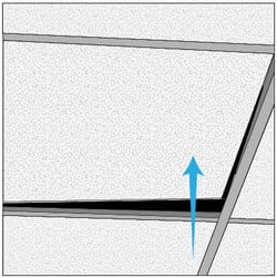
3. Prepare ceiling T-bar

Position a ladder under the mounting spot. Lift and move the ceiling tiles aside to access the T-bar grid.

Step 3 of ceiling installation: preparing ceiling T-bar.

4. Secure the mounting bracket to the T-bar

  • Hold the mounting bracket up against the T-bar.
  • Rotate each T‑bar clip so it hooks securely over both edges of the T‑bar.
  • Tighten the side screws on each clip to lock the bracket firmly in place.
Step 4 of ceiling installation: securing the mounting bracket to the T-bar.

5. Route the Ethernet cable

Run the Ethernet cable through the ceiling and down through the center opening of the mounting bracket.

💡 Tip: You may need to notch the ceiling tile slightly to allow it to lay flat after routing the cable.

Plug the Ethernet cable into the port on the back of the microphone pod before mounting it.

Step 5 of ceiling installation: attaching the microphone pod to the ethernet cable.

💡 Tip: For added security, you can attach a security wire or tether through the small hole in the metal frame on the back of the microphone pod.

 Alternate ceiling installation method for the Nureva HDX microphone pod.

6. Mount the microphone pod

  • Align the widest sections of the keyhole openings on the back of the microphone pod with the pegs on the mounting bracket.

  • Press the pod upward onto the bracket, then slide it in the direction of the Nureva logo until it is securely in place.

Step 6 of ceiling installation: sliding and securing the microphone pod into place.

7. Connect to system hub

Connect the other end of the Ethernet cable to any HDX audio input port on the system hub.

See Connecting components.

Ethernet cable connecting the Nureva HDX microphone pod to the system hub.

Wall mount

The following steps for mounting on the wall can also be followed for directly mounting on the ceiling.

1. Plan the mounting location

Choose a suitable location on the wall for optimal audio pickup.

Refer to HDX placement for guidance on locations.

Wall mount placement guide template for the Nureva HDX microphone pod.

2. Mark for installation

Position the mounting bracket on the wall in the chosen location.

Trace the two center oblong holes in the mounting bracket with a pencil or pen to mark drill points.

Step 1 of wall installation: Mark the wall for mounting bracket installation.

3. Mount the bracket

Ensure the drill points are level vertically, drill the holes, insert wall anchors if needed and secure the mounting bracket with screws.

Step 2 of wall installation: mounting the bracket.

4. Route the Ethernet cable

Run the Ethernet cable to the mounting area and plug it into the back of the microphone pod.

💡 Tip: For clean cable management, route cables through the wall and out the center of the mounting bracket, or surface‑run and conceal them behind the microphone pod.

Step 3 of wall installation: routing the cable for the microphone pod.

💡 Tip: For added security, you can attach a security wire or tether through the small hole in the metal frame on the back of the microphone pod.

Step 4 of wall installation: attaching the safety tether to the microphone pod.

5. Attach the microphone pod

  • With the Nureva logo at the bottom end of the microphone pod, align the widest parts of the keyhole openings on the back with the mounting bracket pegs.

  • Press the microphone pod onto the bracket and slide it down until it is securely in place.

Step 5 of wall installation: securing the microphone pod to the wall mount.

6. Connect to system hub

Connect the other end of the Ethernet cable to any HDX audio input port on the system hub.

See Connecting components.

Ethernet cable connecting the Nureva HDX microphone pod to the system hub.

VESA mount

HDX microphone pods may be installed using VESA standard mounting solutions, including ceiling extension mounts, wall mounts, display mounts and other supported structures. Follow the mount manufacturer’s instructions. All the applicable microphone pod installation guidelines above still apply — a VESA standard mount may be used in place of mounting on the ceiling or wall but the instructions above should still be followed as well as microphone placement guidelines.

Mounting considerations:

  • Verify the mount is rated to support the weight of the HDX microphone pod.
  • Confirm stability for wall, ceiling or extended‑mount installations.
  • For floor stands. confirm the base is stable and resistant to vibration.
  • Always follow the mount manufacturer’s specifications.

Microphone pod FAQs

Can I install the HDX microphone pod horizontally on the wall?

Yes. The HDX microphone pod can be installed horizontally. However, the microphone pod is more securely mounted when it is installed vertically, as the keyhole design on the back, used with the included mounting bracket, is positioned for vertical orientation. For horizontal wall installation, a third-party mounting solution, such as a VESA standard mount, is recommended.

What type of Ethernet cable does the HDX microphone pod require?

Each HDX component (audio bar and microphone pod) requires an Ethernet cable that meets the following specifications: CAT5e or higher, unshielded twisted pair (UTP) and 24 AWG (solid copper). Nureva recommends using cabling and wiring that is in accordance with the applicable national, regional and local electrical codes or ordinances.

System hub installation

The system hub can be placed on a table, shelf or rack, or it can be mounted on a wall.

✍️ Note Ensure you review System hub placement requirements before installation.
HDX system hub table rack mounting installation instructions.

Table, shelf or rack placement

nureva-hdx-system-hub-wall-mount

Wall mounted

What’s in the box

Nureva HDX system hub shown at an angle as an in-box component.
System hub
Mounting clip included with the Nureva HDX system hub.
Mounting bracket
Antenna included with the Nureva HDX system hub.
Bluetooth® antenna
Power supply unit included with the Nureva HDX system hub.
Power supply
Power cable included with the Nureva HDX system hub.
Power cable
Set of Euroblocks included with the Nureva HDX system hub.
Euroblock connectors x6
USB cable included with the Nureva HDX system hub.
USB cable with USB-C to USB-A adapter
Nureva HDX system hub remote control.
Remote control with AAA batteries

What you’ll need

Additional items when mounting to the wall:

  • Screwdriver
  • Drill
  • Anchors: #10 panhead or M5 panhead minimum (x2)
  • Screws: #10 panhead or M5 panhead minimum (x2)
  • Pencil or pen for marking

Table, shelf or rack

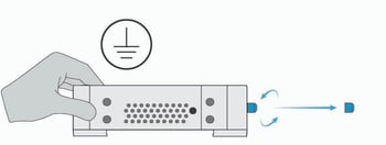
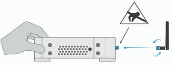
1. Install the Bluetooth antenna

  • Hold the system hub to equalize the static charge and then remove the protective cap from the Bluetooth antenna connector.

  • Thread the Bluetooth antenna onto the connector, tighten until it’s snug and orient it upright for optimal performance.

⚠️ Warning — Avoid touching the connector or inner pin as doing so can damage the system hub.

✍️ Note: If it’s preferred Bluetooth LE is not enabled, leave the antenna off and ensure the protective cap remains in place.

Diagram showing the cap/cover being attached to the Nureva HDX system hub..Diagram showing the antenna being attached to the Nureva HDX system hub.

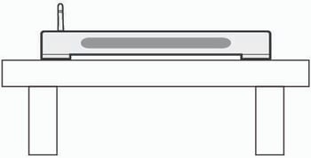
2. Place the system hub on a sturdy table, shelf or rack

✍️ Note: Ensure adequate airflow clearance on all sides. Refer to the HDX placement guidelines.

Step 1 of HDX system hub installation: positioning the system on a table or rack.

Wall mount

1. Mark for installation

Position the mounting bracket vertically on the wall at the chosen location and mark the drill points using a pencil or pen.

Step 3 of HDX system hub installation: driving screws into the mounting bracket.

2. Install the mounting bracket

Ensure the drill points are level, drill the holes, insert anchors if needed and secure the mounting bracket with screws.

Step 2 of HDX system hub installation: mounting bracket to wall.

3. Install the Bluetooth antenna

  • Hold the system hub to equalize the static charge and then remove the protective cap from the Bluetooth antenna connector.
  • Thread the Bluetooth antenna onto the connector and tighten until it’s snug.

⚠️ Warning — Avoid touching the connector or inner pin as doing so can damage the system hub.

✍️ Note: If it’s preferred Bluetooth LE is not enabled, leave the antenna off and ensure the protective cap remains in place.

Diagram showing the cap/cover being attached to the Nureva HDX system hub..

Diagram showing the antenna being attached to the Nureva HDX system hub.

4. Clip the system hub onto the mounting bracket.

Ensure the antenna is vertically oriented and the LED indicator lights are facing forward.

✍️ Note: Ensure adequate airflow clearance on all sides. Refer to the HDX placement guidelines.

Step 4 of HDX system hub installation: mounting the hub onto the bracket.

System hub FAQs

Can I mount the HDX system hub on the wall?

Yes. The HDX system hub comes with a mounting bracket for wall installation. The orientation should be vertical, with the Nureva logo at the bottom and the antenna at the top.

How do I connect the HDX system hub with the audio bars and microphone pods?

The HDX system connects to each component (audio bar and microphone pod) with an Ethernet cable (which you will need to supply). Ethernet cables should be CAT5e or higher, unshielded twisted pair (UTP) and 24 AWG (solid copper). Nureva recommends using cabling and wiring that is in accordance with the applicable national, regional and local electrical codes or ordinances.

Connecting components

✍️ Note Ethernet cables are required to connect the audio bars and microphone pods to the system hub and connect the system hub to the network.

Ethernet cable requirements

HDX does not include Ethernet cables for connecting the system hub to the audio bars and microphone pods and connecting the system hub to the network. Nureva recommends using cabling and wiring that is in accordance with the applicable national, regional and local electrical codes or ordinances.

Nureva recommends Ethernet cables are:

  • CAT5e or higher
  • UTP (unshielded twisted pair)
  • 24 AWG (solid copper)


HDX connection steps

HDX system connection diagram showing audio bars, microphone pods, the system hub, a computer, and a network switch wired together.

1. Connect the network cable

  • Plug an Ethernet cable into a network connection port on the back of the system hub.

  • Plug the Ethernet cable into an available port at the network access point.

✍️ Note: If the system hub is not connected to an external network, updates must be done manually.

Rear panel of the HDX system hub with the network cable port highlighted in blue.

2. Connect the audio bars and (if applicable) microphone pods

  • Plug Ethernet cables from each HDX component (audio bars and microphone pods) into the audio input ports on the back of the system hub.

Rear panel of the HDX system hub with the HDX audio input ports highlighted for connecting audio bars.

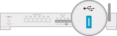
3. Connect the computer or appliance

The HDX system can now be connected to a computer or a conferencing device:

  • Plug the USB-C cable (provided) into the USB-C port on the back of the system hub.

  • Plug the other end of the USB-C cable into a USB-C port on the computer or conferencing device.

A USB-C to USB-A adapter is included, if required.

Rear panel of the HDX system hub with the USB port highlighted for connecting a computer.

It is recommended that all HDX components be physically installed in the room before connecting the system to the power supply.

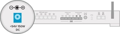
4. Connect the power supply

⚠️ Warning — risk of equipment damage: Do not plug or unplug Ethernet cables running from the audio bars and microphone pods to the system hub while the system hub is powered on. Doing so can permanently damage the system.

Rear panel of the HDX system hub with the 54V 150W DC power supply port highlighted.

Calibrating HDX

Calibration tunes the HDX system to the unique acoustics of your room. Running calibration ensures optimal microphone pickup and speaker performance so every conversation sounds clear and natural.

To calibrate the HDX system, press the calibrate button on the front of the system hub. The calibration sounds will start immediately.

When the calibration sequence has finished, your remote can be paired and a system update will be required.

⚠️ Warning — HDX calibration is loud: A static like sound will play for up to 45 seconds. Cover your ears or wear hearing protection. Remain quiet and still until calibration finishes.

Warning icon of a person covering their ears, indicating loud audio during HDX system hub calibration.
Front panel of the HDX system hub shown with the audio calibration icon.

Pairing the remote

The remote will automatically attempt to pair with the system hub after the remote’s batteries have been inserted. To disconnect the remote from the system hub, press and hold the customizable button 2 and volume-down button 4 simultaneously for 3 seconds. This will clear any existing connection. To pair the remote with the system hub again, press any button to initiate the pairing process.

Pairing the remote is only possible when the Bluetooth antenna is attached. 

Updating HDX

An update will be required when setting up an HDX system for the first time to ensure all features function as intended. Keeping the HDX system up to date also helps maintain performance, security and access to the latest audio features and improvements.

⚠️ Important — Do not interrupt system updates Do not unplug or power off the HDX system while an update is in progress. Interrupting an update can damage the system software and may require service intervention.

To learn about network requirements for updates, see network requirements.

First-time update

For the initial setup, update the HDX system over USB using a computer that is connected to the internet.

Update steps

  1. Plug the provided USB-C cable into the USB-C port on the system hub.
  2. Plug the other end of the USB-C cable into a USB-C port on the computer.
    - A USB-C to USB-A adapter is included, if required.
  3. Open a web browser and enter 169.254.253.253 in the address bar.
  4. When prompted, enter the unique code printed on the bottom of the system hub.
    - This code (format XXX-XXX-XXX) is the default password for accessing the Nureva App.
    - You can change the password later in Settings.
  5. The Nureva App opens in the browser. Press the Update button.
  6. Follow the on-screen instructions and keep the system powered on until the update is complete.

Learn more about all HDX update options.

Once the update is complete, the HDX system is ready for use. We recommend placing a test call to confirm optimal audio performance for both remote participants and in-room users. Verify that the HDX system is selected as the default audio device in your operating system as well as in your UC&C or audio conferencing application.

The HDX system can be managed locally through the Nureva App and enrolled in Nureva Console to remotely monitor and manage it from anywhere.

Ecosystem and integrations


Adding physical integrations

Using auxiliary ports on an HDX system 

HDX comes with auxiliary ports on the system hub. They are used to send and receive audio streams to and from third-party devices. The auxiliary port options are found in the Nureva App (Devices) and Nureva Console (Settings).

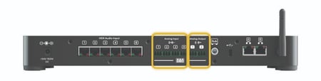
The back of the system hub has six Euroblock connections:

  • Four inputs:
    • Default level: 4 dBu (1.23 Vrms)
    • Input impedance: ≥ 10 kΩ
  • Two outputs:
    • Maximum level: 4 dBu (1.23 Vrms)
    • Output impedance: ≤ 100 Ω

Rear panel of the HDX system hub with the auxiliary analog input and output ports highlighted in yellow.

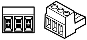
Euroblock connectors

These 3-pin connectors are for balanced (differential) signals (positive, negative and ground). These inputs and outputs can be configured in the Nureva App or Nureva Console when adding a device.

Diagram of a Euroblock (Phoenix) connector showing positive, negative, and ground terminals.

Replacement terminal blocks can be obtained, as long as they are Euroblock compatible, 3.5 mm pitch and a plug type. The connectors provided with HDX are manufactured by Same Sky, part number TBP03P3-350GR.

Adding analog inputs

The four analog inputs can be configured as individual mono inputs or as stereo inputs. To configure as stereo, the pairs must be inputs 1 and 2 or 3 and 4.

Use the Nureva App to add new analog input devices to your HDX system. Learn more.

Rear panel of the HDX system hub with the analog audio input port highlighted in yellow.

Adding analog outputs

HDX supports third-party speakers. However, there may be limitations on the number of external speakers that can be used, and consideration will be needed regarding speaker and microphone placement.

UC&C platforms

HDX works with all leading UC&C platforms — the system hub is connected to the audio conferencing device with a USB cable.

Learn more

The default setting in the Nureva App is optimal for Microsoft® Teams Rooms. This setting can be switched to Zoom Rooms.

Developer Toolkit APIs

The Nureva Developer Toolkit gives you access to cloud-based and local APIs. You can integrate Nureva devices with other products to save time and automate tasks.

Nureva’s APIs include:

  • Device management API
  • Device control API
  • Sound location device API
  • Room data API

Third-party integrations include:

  • Camera tracking
  • Control system

Learn more

Network requirements

The HDX system hub has two network ports that provide connection with the Nureva App and Nureva Console for device management, updates and monitoring. These Ethernet ports support integrations with room control systems and camera systems and they support AVoIP with 2x2 channels to send or receive audio over the LAN to external audio systems.

✍️ Note Nureva Console connections are both inbound and outbound initiated. These are bidirectional, nonpersistent connections.

Configuration tips

  • Ensure port 8883 is open and the MQTT protocol is allowed on your network.
  • Ensure the network uses Dynamic Host Configuration Protocol (DHCP) to assign the Internet Protocol (IP) address.
  • Note that HDX does not support proxy server configurations.
  • Ensure port 123 is open and the Network Time Protocol (NTP) is allowed on your network.
  • Note that static IP addresses are not supported by HDX at this time.

When enhanced internet security measures or firewalls are being used, some URLs and IP addresses will need to be approved to allow for a steady connection.

URLs to approve

Service URLs
Configuration https://app.launchdarkly.com
https://clientstream.launchdarkly.com
https://events.launchdarkly.com
https://stream.launchdarkly.com
Firmware updates https://nurevaproddistribution.blob.core.windows.net
https://versions.nureva.com
Device enrollment to Nureva Console https://account-management-service.nureva.com
IoT Hub gateway-iothub-prod.azure-devices.net
Needs either port 8883 for MQTT protocol or port 443 for SSL
System software updates https://api.snapcraft.io
https://assertions.ubuntu.com
https://cloudfront.cdn.snapcraftcontent.com
https://login.ubuntu.com
Telemetry https://dc.applicationinsights.azure.com
https://dc.applicationinsights.microsoft.com
https://dc.services.visualstudio.com
Ad blocking breaks telemetry functionality (continuous connection)
NTP ntp.ubuntu.com

IP addresses to approve

Service IP address
LaunchDarkly 18.209.243.58
(events.launchdarkly.com)
Microsoft  services 20.166.40.71
Microsoft  Azure cloud 20.50.65.88
Microsoft  Network management, load balancing 20.9.155.145
Microsoft  Network management, load balancing 20.9.155.148
Microsoft  Network management, load balancing 20.9.155.150
Amazon Web Services (AWS) 23.23.137.6
Amazon Web Services (AWS) 3.229.64.113
Amazon Web Services (AWS) 3.231.244.68
AWS Network management, load balancing 3.209.131.209
AWS  Network management, load balancing 3.215.101.233
AWS  Network management, load balancing 3.218.251.176
AWS  Network management, load balancing 3.224.157.225
Amazon Web Services (AWS) 52.84.90.126
Amazon Web Services (AWS) 54.147.5.20

Troubleshooting

Quick troubleshooting steps to resolve most common issues:

  • Power: Ensure the HDX system is powered on and it is plugged into a working power source. Resetting the power will often address small issues. Unplug the AC power adapter cable from the port of the system hub. Wait about 30 seconds before plugging it back in.

  • Cables: Verify all cables are securely connected to the system hub, audio bars and microphone pods. Check Ethernet cable requirements to ensure cable types are supported.

  • Network connection: Check the external network connection, which allows the HDX system to automatically update and have access to the latest features. The system can also be manually updated using the Nureva App, but this requires the HDX system to be connected to the network.

  • Microphone pickup: If the HDX system has been moved or the room layout has changed, a quick calibration will often resolve audio issues.

  • System hub LEDs: The status indicator lights on the front and back of the system hub can help when troubleshooting issues with the system and confirming the device is ready to be used.

  • Nureva App: Monitor the health of your HDX system in the Nureva App and perform key troubleshooting actions, such as update, calibrate, restart and check device connections. Learn more.

Previous section

️ ← HDX placement