February 15, 2023
Unified coverage map: a radically better technology for hybrid spaces
Posted by Erica Yorga on Feb 15, 2023 6:00:00 AM
This blog is part of a series that takes a deep dive into the science behind Microphone Mist™ technology. The series also includes Continuous echo cancellation. This is what clarity sounds like, A groundbreaking approach to gain control that cuts conference call annoyance and Why thousands of virtual microphones matter — acoustic spatial resolution in a 3D space. Each piece originally appeared in audioXpress magazine.
The rise of hybrid working and learning has brought challenges for anyone who equips and maintains shared spaces. The demands in meeting rooms, boardrooms, open spaces, collaboration spaces and classrooms are constantly evolving.
In many cases technology, and how it is embedded in the systems to support these spaces, has become more complex, requiring greater technical know-how to work with it. The need to manually configure and change out equipment is outdated. Reducing system design, installation and commissioning overhead along with technical management and complexity is paramount, especially for organizations that are trying to simplify and reduce costs as they are deploying tens, hundreds and even thousands of systems.
How can applying innovative thinking to the technology and how it is embodied in products provide a fresh, adaptive approach to evolving requirements and spaces? Audio conferencing systems should be easy to install and then automatically configure and optimize themselves for the room.
Nureva’s unified coverage map, a feature of patented Microphone Mist technology, takes a radically different approach by providing automated configuration capabilities that result in consistently optimized audio performance and reduced total cost of ownership. Technology has evolved, and organizations now need to support increasing numbers of remote participants who demand reliable and consistent far-end audio performance. The unified coverage map was designed to meet this need.
The large-room conferencing challenge
The challenges that come with using legacy audio conferencing technology aren’t always apparent in small spaces that only require one audio device.
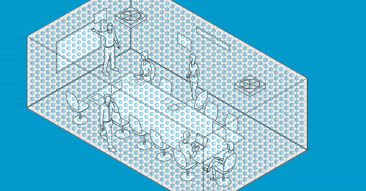
The installation, configuration and optimization of a single conferencing device can be straightforward (Figure 1a). In small spaces, where one device is sufficient, room coverage and setup may not be an issue. Figure 1b shows how Microphone Mist technology also provides full-room coverage in smaller spaces, using thousands of virtual microphones.
But for legacy microphone array systems, their inherent complications become readily apparent as room size increases. These systems require decisions to be made about the number of array devices and their placement relative to the type of room coverage needed, along with any inter-device spacing requirements.
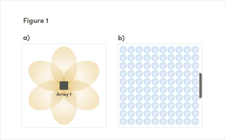 Figure 1: The disparate coverage zone for legacy systems (a) and a unified coverage map using the Nureva® systems (b) are shown here.
The old approach
In legacy systems, each array device operates independently and is responsible for a specific area and coverage pattern, resulting in overlap that needs to be minimized (Figure 2a). This requires technical specialists with detailed knowledge about acoustics and each device’s specific capabilities. Parameters such as number of active zones and beam width and shape all need to be configured for each device.
To manage the audio pickup and processing decisions, a third device is required – a digital signal processor (DSP). The DSP determines how to mix and match audio outputs of the array devices to provide room coverage and audio processing functions, such as Acoustic Echo Cancellation (AEC), gain structure (GS), noise reduction (NR), equalizer (EQ) and coverage zone configurations. These functions may be configurable on the individual devices or in the DSP unit.
As incremental devices are added to the system, there is typically no awareness among the devices to automate device adoption and the configuration process. Each device is treated as a separate, stand-alone device with capabilities that need to be manually integrated into the DSP.
This time-consuming and technically involved process of configuring system components is how it has been done historically; but in modern hybrid spaces customers need/demand more. Systems that require manual configuration of separate DSPs, microphones and speaker devices for even the simplest of installations don’t fit with the challenges of modern, hybrid working and learning spaces. It’s time for a change.
A fresh approach
We believe that large-room audio systems should have the same minimal set up and configuration and great performance as small rooms. We leveraged our Microphone Mist technology and augmented it with a new unified coverage map to deliver an automatically configured conference system that scales from small to larger spaces. This approach blows up legacy paradigms and sets the stage for successful and cost-efficient deployments.
The unified coverage map maintains the advantages of a uniform virtual microphone coverage map solution (already available with Nureva’s single array devices) and scales it to seamlessly adapt in small to large rooms (Figure 2b). It enables the physical microphones from two devices to work together, creating a combined microphone array that covers the entire room. The overall installation and system commissioning process remains the same – it’s minimal.
With Nureva’s unified coverage map, patent-pending calibration signals are used to derive a real-time system configuration and an optimized room coverage map without the need for technician level know-how. And this happens automatically when the system powers up. The result is a dynamically created unified coverage map that is adapted to the device locations. Unlike legacy systems (Figure 2a), the coverage map looks identical in shape and distribution in both small and large rooms. There is no device and coverage zone overlap to consider and manage.
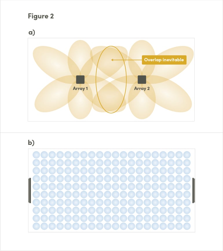 Figure 2: The disparate coverage zones for legacy systems have an inevitable overlap (a); while the Nureva systems have a unified coverage map (b).
Why use a single unified coverage map?
The optimal way to provide the best room coverage and audio performance would be to install a large 3D microphone array with hundreds or even thousands of physical microphones spread throughout the room. Of course, this is not practical given the cost and complexity. But Nureva’s unified coverage map is the next best thing. There are many benefits to our approach that overcome the limitations of legacy systems.
Targeting conflicts between disparate array devices and zones are eliminated. Each virtual microphone has a unique location with no coverage overlap that requires blending (mixing) and sharing decisions, so the targeting and audio signal path is clean and optimized for all locations in the room.
All physical microphones are available to provide gain to any virtual microphone in the room, meaning consistent talker and background noise levels with significantly reduced noise artifacts and system distortions. This differs from legacy systems that limit gain to a single array device or zone, creating uneven gain and background noise levels and inter-device distortion artifacts.
Remote participants hear a consistent and natural tonal quality for each in-room talker because there are no handoffs between devices or zones that may be configured differently. For example, differing zone beam widths (wide, medium or narrow) can have inconsistent and detrimental effects on the sound quality at the far end of the call.
Because each virtual microphone location uses the same audio processing chain, the chain is simplified, optimized and stable. It eliminates unexpected configurations and behaviors that can occur with a hierarchical or cascaded audio process chain where each device does its own audio processing.
Individual virtual microphones do not overlap and therefore can have unique targeting parameters applied to ignore or enhance fixed positional-based sound sources in the room, such as HVAC vents and fans. This makes it much easier to effectively manage undesired sound sources. If an HVAC vent is situated between two coverage zones in a legacy system, each device in the system will need to deal with the unwanted noise source. If the undesired sound source is in the middle of a broad zone, it impacts all desired sounds in the zone negatively.
People moving and talking at the same time is easily managed with the unified coverage map. One virtual microphone with a set position never conflicts or overlaps with another virtual microphone with its own unique position. The talker easily moves between virtual microphones as only the focusing parameters need to adjust, resulting in consistent audio performance. With legacy systems, zone and device coverage overlap are often difficult problems to deal with, necessitating complex handoff and decision logic and combining different audio processing chains.
Placement of the physical array devices is not as critical. With legacy systems, each array device becomes responsible for a very specific area of the room with its own coverage map and configuration. With the unified coverage map, the additional device is incorporated into the physical array, providing gain and increased coverage map support. It is like adding more horsepower instead of adding a second engine to drive a second wheel.
Commissioning time makes all the difference
These benefits make a significant difference in required commissioning time and cost. With legacy systems, room size and complexity often require a lengthy commissioning process. But with the automated, unified coverage map, the whole process takes only a few minutes. As the number of rooms increases, the savings in technician costs add up fast.
With a legacy audio conferencing system, the complexity of configuration and commissioning increases when new devices are added (Figure 3a), leading to many hours of work for a specialized technician. In step 1, a manual configuration of the network and device parameters may be required, with some systems needing their own dedicated local room network. Once configured on the network, each virtual audio path connection from device to DSP is completed by the technician (step 2), which can be a complex and detailed technical task. In step 3, the system coverage patterns and shapes need to be configured for each device, taking into account microphone array device type and location, available coverage patterns, number of zones, zone overlap and beam widths. In step 4, the technician must review the audio parameters for each device to determine if specialized parameters, such as AEC, EQ, NR, delay and gain, are needed for each device or if global parameters are sufficient. Then thorough testing, step 5, is required to determine if the correct setup choices were made. If needed, adjustments and calibrations are implemented and then the whole process may have to be repeated until the system achieves the required performance and the commissioning is complete.
Nureva’s unified coverage map dramatically simplifies this process (Figure 3b). The first step is to plug in all devices and turn the system on. In step 2, the system sends patent-pending proprietary calibration signals between each device. This allows the system to locate the two devices in 3D space and then build a combined physical array. The system knows the precise location of each device relative to each other. In step 3, this information is used to dynamically construct the unified coverage map, providing complete coverage matched to the room. Since the individual arrays are seen as one physical combined array, the system can calibrate and optimize for AEC, NR and gain parameters and does not require device-specific hierarchical configurations or blending coverage maps. There is no need for a technician to manually configure and optimize the system at any step of the process.
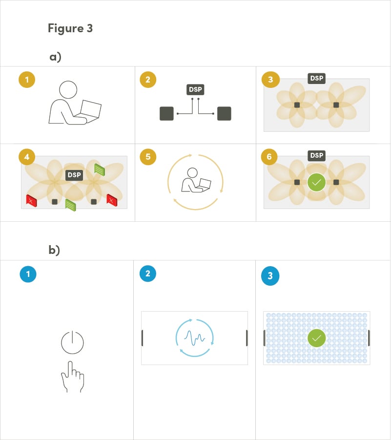
Figure 3: The configuration for disparate coverage zones with legacy systems (a) is compared to the configuration of a unified coverage map with Nureva systems (b).
Optimized audio targeting and processing
The second key differentiator for the unified coverage map relates to audio targeting and processing. While the specifics of the process may vary between different legacy systems, it is clear to anyone who has experience with them that they are too complex. In legacy systems, the challenges and problems are well known and persistent.
The first step with a legacy system is to correctly target a person talking in the room (Figure 4a). With distributed devices and coverage zones, this is a daunting technical challenge. Each array device is responsible for a certain part of the room, and the audio system is required to select the correct individual or combination of devices and zones within the disparate array devices to target the talker. If the talker is located within the overlap between zones or between two array devices, this is a real challenge.
A good analogy for the target problem is what happens when a cell phone call is caught between two or more cell towers. The issues that arise – such as cross talk, messy handoffs, dropped calls and poor voice quality – are similar to what happens when using separate microphone arrays in a legacy conferencing system. They all stem from each individual array (or cell tower) covering its own area with overlapping coverage. The challenge becomes more acute if the talker is mobile and moving throughout the room (or driving between towers). Because each array device works independently, the system must decide how to switch, blend or ignore disparate signals from each device. The legacy conferencing system needs to adapt and constantly make correct targeting and mixing decisions at the DSP to ensure that the far end audio quality stays optimal.
To add to the complexity, the audio processing function may be hierarchical or combined between devices. There may be multiple layers of audio processing depending on how the system is configured, and each array device may do its own gain, EQ and NR processing. Once the signals are received by the DSP, additional processing on top of what the individual array devices have implemented may be completed. The processing may be device dependent, or DSP driven, and it is hard for the customer to know.
This all increases the chance that there will be inconsistent processing and incorrect device configurations and management. The UC&C client will be required to adapt and adjust, leaving the remote participant with inconsistent audio performance. When an organization manages multiple conference rooms, maintaining consistent system audio quality across all rooms may be very difficult to do.
It does not need to be like this. The unified coverage map (and the broader Microphone Mist technology platform) has greatly simplified and optimized the targeting process.
As shown in Figure 4b, first the system locates and focuses on the sound source within the unified coverage map using patented targeting algorithms. There is no need for complex switching between array devices and individual array coverage zones or blending between zones and separate array devices. A large-room installation performs just like a small room.
Once the array is focused on the appropriate virtual microphone within the unified coverage map, Microphone Mist technology proceeds with audio processing. A single combined array focused on one virtual microphone makes for an efficient and optimized audio processing path with no unnecessary inter-device cascading or duplication of processing. The result is consistent and improved acoustic echo canceller, gain structure, background noise and noise reduction performance. It’s no longer necessary to adapt to a different array device that may have its own configuration parameters for AEC, PEQ, NR and gain. The UC&C client will always be presented with a consistent audio signal, and audio performance at the far end of the call will stay optimized. Nureva’s novel architecture simplifies the audio processing chain, regardless of the complexity or size of the room the system is installed in.
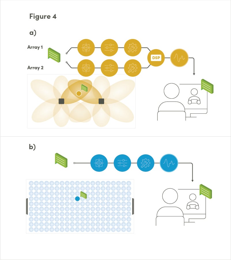 Figure 4: Sound source targeting and processing with legacy systems (a) is shown in comparison with sound source targeting and processing with Nureva systems (b).
Summary
The unified coverage map delivers a consistent, superior audio experience while eliminating the complexity of legacy audio system set up and/or configuration. It automatically adjusts and adapts to the room, significantly reducing the system installation and management burden while optimizing audio in large spaces. It brings a radically new total customer experience into rooms where that was never possible.
As more and more rooms are equipped with audio conferencing products, choosing an approach that scales is only becoming more important. By taking advantage of fresh approaches such as Nureva’s unified coverage map and continuous autocalibration as discussed in my previous audioXpress article, large-room conferencing can be just as simple and effective as small-room conferencing. And that’s exactly what is needed to meet the demands for hybrid working and learning – now and in the future.
Posted by
Erica Yorga
February 15, 2023


